Specifying Line Properties
Use the Horizontal or Vertical Line Properties dialog to precisely specify the width, color, and position of your lines.
To specify the properties of a line
-
Place the cursor anywhere on the line (that is not a sizing handle) and then right-click.
-
Select the Properties command from the popup menu that is then displayed.
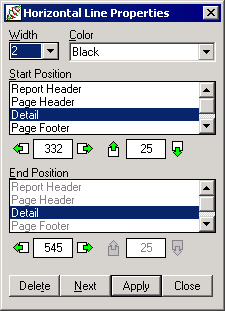
The Line Properties dialog is then displayed, as shown in the following image.

The title bar of this dialog is displayed as Horizontal Line Properties or Vertical Line Properties, indicating whether the currently selected line is horizontal or vertical.
-
Select a line width from the Width combo box. The width sizes are in pixel units. The default value is 2 pixels.
-
Select a line color from the Color combo box. The default color is Black.
If you select the Custom color, the common Color dialog is displayed to enable you to select or define a custom color. When you have made your selection, click the OK button to apply the selected color or click the Cancel button to close the Color dialog without making any changes.
-
Under the Start Position caption, specify the starting position of the line. The list box displays the frame in which the line starts. The position of the line is measured in pixels relative to the top left corner of the designated frame, in the two text boxes below.
-
Select the frame the in which the line starts from the list box under the Start Position caption.
-
Specify the horizontal position of the start of the line from the left edge of the frame in pixels in the horizontal position text box under the Start Position caption.
Alternatively, click on one of the horizontal position buttons to move the start of the line left or right one pixel at a time.
-
Specify the vertical position of the start of the line from the top edge of the frame in pixels in the vertical position text box under the Start Position caption.
Alternatively, click on one of the vertical position buttons to move the line up or down one pixel at a time.
-
-
Under the End Position caption, specify the position of the end of the line. The list box displays the frame in which the line ends. It is disabled for horizontal lines because horizontal lines cannot cross frames. The position of the line is measured in pixels relative to the top left corner of the designated frame, in the two text boxes below.
-
Select the frame in which the line ends from the list box under the End Position caption. Only a vertical line can cross multiple frames.
-
Specify the horizontal position of the end of the line from the left edge of the frame in pixels in the horizontal position text box under the End Position caption. This text box is disabled for a vertical line because the horizontal position of the end of a vertical line is always the same as that of the start.
Alternatively, click on one of the horizontal position buttons to move the end of the line left or right one pixel at a time.
-
Specify the vertical position of the end of the line from the top edge of the frame in pixels in the vertical position text box under the End Position caption. This text box is disabled for a horizontal line because the vertical position of the end of a horizontal line is always the same as that of the start.
Alternatively, click on one of the vertical position buttons to move the line up or down one pixel at a time.
A line can be moved within a frame by changing the relevant top and left values, and moved between frames by changing the start and end frames. For the end frame, the frames that come before the selected start frame are disabled, as the end frame must be the same as or below the start frame. If you change a line start or end value so that it is greater or less than the corresponding end or start value, the start and end positions are reversed in the dialog, to maintain their relative values.
-
-
Click the Apply button to apply your changes immediately to the currently selected line.
-
Click the Delete button to delete the currently selected line.
-
Click the Next button to select the next line or box. Lines and boxes are selected in the order in which they were defined. This can be useful when an existing drawing object is too small to be easily visible.
-
Click the Close button to close the Line Properties dialog and return to the report layout.